| |
|
Installing the new drive |
 |
|
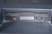
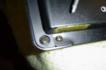
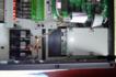
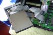
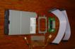
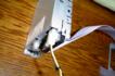
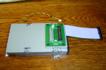
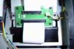
Into the bezel
The complete assembly was then lowered into position and eased through the bezel hole. |
 |
Click to enlarge... |
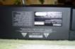
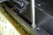
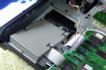
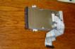
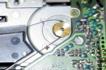
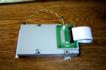
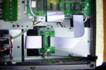
Checking the ribbon
The ribbon cable comes from underneath the floppy drive and is very close to the bottom of the bezel. I checked that all was well, and realised that this was the only possible arrangement of the ribbons. [Click on the picture for an enlarged view and more detailed description.] |
 |
|
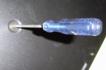
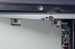
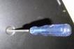
Screw into place
I then screwed the new assembly into place, and connected the final piece of ribbon cable into the adapter board. |
 |
|
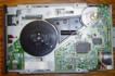
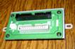
Final ribbon
The other end of the ribbon cable was then pushed into place on the main circuit board. . |
 |
Click to enlarge... |
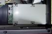
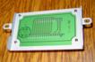
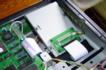
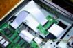
Planning the tidy-up
The replacement drive assembly was now in place and connected up. I could now think about how to tidy the ribbon cable up - all the other ribbons in the SY99 were carefully arranged with right angle flat bends produced by a single 45 degree fold, and I wanted to continue this manufacturing practice here. [Click on the picture for an enlarged view and more detailed description.] |
 |
|
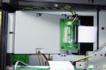
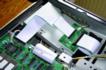
Tidying up the ribbon
After a bit of planning, I put a deliberate 45 degree bend in the ribbon, and a 'z' bend to take up the slack as the ribbon goes to the drive adapter board. |
 |
|
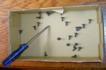
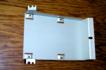
Screws back in place
The remaining self tapping screws were then used to put the metal plate back in place. I like to start at the centre of the plate and leave all the screws loose until they are all in place. Then I start at the centre of the plate and tighten those, then work my way outwards from the centers of each of the long sides, ending up with the final screws in the centre of the end cheeks.I took care not to force the self-tapping screws - if they didn't go in easily, then I reversed the screwdriver and tried again until I found a thread starting position that went in smoothly and easily. |
 |
|
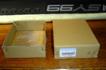
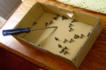
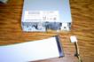
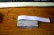
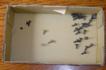
Empty box lid
Theoretically, the box lid at this point should be empty. Luckily, when I looked, it didn't look like this! |
 |
|
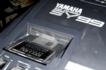
Verify and test
All done! All that remained now was to check that the drive works by formatting a blank floppy disk and doing a 'Save All' followed by a test load of a sequencer file. Everything worked! Mission Accomplished. My only niggle is the green LED which replaces the previous red one, but I'm sure I will get used to it. |